Summary of the structure of the transformer and the functions of each component
1. Core: The core is the magnetic circuit part of a transformer. To reduce the hysteresis and eddy current losses of the core under the action of alternating magnetic flux, the core is made by stacking high-quality silicon steel sheets with a thickness of 0.35mm or thinner. At present, cold-rolled grains with high magnetic permeability are widely used in factories to replace silicon steel sheets, which can reduce the volume and weight, and also save wires and lower the heat loss caused by wire resistance.
The core consists of two parts: the core column and the yoke. Winding is wound over the core column, and the yoke connects the core column to form a closed magnetic circuit. According to the arrangement of windings in the core, transformers are divided into two types: core type and shell type (or simply core type and shell type). Single-phase two-core column. This type of transformer has two core columns. The upper and lower yokes connect the core columns to form a closed magnetic circuit. Both core columns are fitted with high-voltage windings and low-voltage windings. Generally, the low-voltage winding is placed on the inner side, that is, close to the core, while the high-voltage winding is placed on the outer side. This makes it easier to meet the insulation grade requirements.
Core-type three-phase transformers come in two structures: three-phase three-core column type and three-phase five-core column type. The three-phase five-core column type (also known as the three-phase five-column type) is also called the three-phase three-core column side yoke type. It is composed by adding two side yokes (cores without windings) on the outside of the three-phase three-core column (also known as the three-phase three-column type), but the cross-sections and heights of the upper and lower yokes are smaller than those of the ordinary three-phase three-column type. Thereby reducing the height of the entire transformer.
Three-phase three-core column, it is to place the three windings of the three phases respectively on three core columns, and the three core columns are also connected by upper and lower iron yokes to form a closed magnetic circuit. The layout of the windings is the same as that of a single-phase transformer. The three-phase five-core column, compared with the three-phase core column, has two additional branch core columns on the left and right sides of the core column, which are called side chokes. The windings of each voltage level are respectively wound in phase on the three middle core columns, while the side yoke has no windings. Thus, a three-phase five-core column transformer is formed.
Since the magnetic flux of each phase in a three-phase five-column core can be closed through the yoke, the three-phase magnetic circuits can be regarded as independent of each other, unlike the interrelated magnetic circuits of each phase in a common three-phase three-column transformer. Therefore, when there is an asymmetric load, the zero-sequence magnetic flux generated by the zero-sequence current of each phase can be closed through the side yoke, so its zero-sequence excitation impedance is equal to the excitation impedance (positive sequence) during symmetrical operation.
Three-phase transformers of medium and small capacity all adopt the three-phase three-column type. Large-capacity three-phase transformer. Often restricted by transportation height, the three-phase five-column type is mostly adopted.
An iron shell single-phase transformer has one central iron core column and two branch iron core columns (also known as side yokes), and the width of the central iron core column is the sum of the widths of the two branch iron core columns. All windings are placed on the central core column, and the two branch core columns are like "shells" surrounding the outside of the windings, thus it is called a shell transformer. Sometimes it is also called a single-phase three-column transformer.
The iron shell three-phase transformer can be regarded as having its core composed of three independent single-phase shell transformers placed side by side.
The core-type transformer has a relatively simple structure. The distance between the high-voltage winding and the core is relatively far, and the insulation is easy to handle. The structure of shell-type transformers is relatively sturdy, but their manufacturing process is rather complex. The distance between the high-voltage winding and the core column is relatively close, making insulation treatment more difficult. The shell structure is easy to enhance the mechanical support for the windings, enabling them to withstand relatively large electromagnetic forces. It is particularly suitable for transformers carrying large currents. The shell structure is also used in large-capacity Power Transformers.
In large-capacity transformers, to ensure that the heat generated by the core loss can be fully carried away by the insulating oil during circulation, thereby achieving a good cooling effect, cooling oil channels are usually set up in the core. The direction of the cooling oil passage can be made parallel or perpendicular to the plane of the silicon steel sheet. 2. Winding
The arrangement form of the windings among each other on the core
The windings of a transformer, based on the arrangement of its high-voltage and low-voltage windings on the core, have two basic forms: concentric and overlapping. Concentric winding: Both the high-voltage winding and the low-voltage winding are made in a cylindrical shape, but the diameters of the cylinders are different, and then they are coaxially wound around the core column. The overlapping winding, also known as the cake winding, has its high-voltage winding and low-voltage winding each divided into several wire cakes, which are arranged alternately along the height of the core column. Interlaced windings are mostly used in shell-type transformers.
Core-type transformers generally adopt concentric windings. Usually, the low-voltage winding is assembled close to the core, while the high-voltage winding is placed outside the low-voltage winding. There are certain insulation gaps and heat dissipation oil channels between the low-voltage winding and the high-voltage winding as well as between the low-voltage winding and the core, which are separated by insulating paper tubes.
Concentric windings can be further classified into several types based on their winding characteristics, such as cylindrical, helical, continuous and tangled types.
(a) Cylindrical winding
The cylindrical winding is the simplest type of winding. It is made by continuously winding insulated wires along the height direction of the core. After the first layer is wound, Place the insulating paper between the first layer and then wrap the second layer. This kind of winding is generally used for the low-voltage winding of small-capacity transformers.
(b) Helical winding
The above-mentioned cylindrical winding is actually also of the helical type. However, the helical winding mentioned here has a larger number of wires connected in parallel per turn. It is made by arranging multiple insulated flat wires in parallel along the radial direction (one wire pressing on one), and then winding them one by one along the axial height of the core column like a thread, with each turn acting like a reel.
When there are too many parallel conductors, the parallel conductors are divided into two rows and wound into a double helical winding. To reduce the additional losses in the wires, when winding helical windings, the parallel wires need to be swapped. This type of winding is generally a high-current winding with a three-phase capacity of 800kVA or less and a voltage of 35kV or less.
(c) Continuous winding
Continuous winding is composed of several wire reels (also known as wire discs) made by continuously winding flat wires. The connection between adjacent reels is alternately made on the inner and outer sides of the winding, and both are naturally connected by the wires used to wind the winding, without any joints. This type of winding has a wide range of applications and is generally used for windings with a three-phase capacity of 630kVA or more and a voltage ranging from 3 to 110kV.
(d) Tangled winding
The shape of the tangled winding is similar to that of the continuous winding. The main difference is that in the continuous winding, the electrically adjacent turns in each coil are arranged in sequence, while in the tangled winding, another turn in the winding is inserted between the electrically adjacent turns to increase the actual potential difference between adjacent turns. The tangled type winding assembly has many welding heads and takes a long time to wind. The purpose of using the tangled winding is to increase the longitudinal capacitance of the winding, so that when overvoltage occurs, the initial voltage can be distributed more evenly among the turns of the wire. Tangled windings are generally used for high-voltage windings with voltages above 110kV.
The winding is the main heat-generating component during the operation of a transformer. To effectively dissipate heat from the winding, in addition to having oil channels on the inner and outer sides of the winding in the longitudinal direction, for double-layer cylindrical windings, insulating struts are often used to separate the inner and outer layers to form longitudinal oil channels. For parallel coil windings, such as helical, continuous, and tangled windings, insulating strips are also used to separate each two coils, forming a transverse oil passage. The longitudinal and transverse oil channels communicate with each other.
2) Winding structure type (a) Winding structure type of ordinary transformer
Transformers are classified by the number of windings in each phase into types with two windings, three windings or more windings. In a three-winding transformer, three windings are concentrically arranged on each core column, namely the high-voltage winding, the medium-voltage winding and the low-voltage winding. Step-up transformers are often used to transfer power from low-voltage windings to high-voltage and medium-voltage power grids. The winding arrangement is as follows: the medium-voltage winding is close to the core, the high-voltage winding is on the outermost layer, and the low-voltage winding is between the medium-voltage winding and the high-voltage winding. The structure of a step-down transformer is that the low-voltage winding is close to the core, the medium-voltage winding is located between the low-voltage winding and the high-voltage winding, and the high-voltage winding is still on the outermost layer. It is often used to transfer the power flow from high voltage to medium voltage and low voltage.
For the start-up dual-purpose transformer of a 600MW unit, when both the high-voltage and two-stage medium-voltage (17.5kV and 3kV) windings are Y connections, to provide a third harmonic current path for the transformer, ensure that the main magnetic flux is close to a sine wave, and improve the waveform of the electromotive force, a fourth Δ connection winding is often set on this transformer, thus becoming a four-winding transformer.
(b) Split transformer winding structure type
In the power supply system of large-capacity units (with a single unit capacity of 200MW or more), when only 6kV first-level factory high voltage is adopted, for safety reasons, the main factory load needs to be supplied by two power lines and two busbars are set up. At this time, split low-voltage winding transformers are often used, which are simply called split transformers. It has one high-voltage winding and two low-voltage windings. The two low-voltage windings are called split windings. In fact, this kind of transformer is a three-winding transformer with a special structure.
The structural feature of a split winding transformer is that the arrangement of windings on the core should meet two requirements: ① There should be a relatively large short-circuit impedance between the two low-voltage split windings; ② The short-circuit impedance between each split winding and the high-voltage winding should be small and equal.
(c) Winding structure type of autotransformer
Autotransformers are often used in some large power plants and substations to connect two high-voltage systems with a relatively small voltage difference.
The working principle of an autotransformer is different from that of a common transformer. There is not only a magnetic connection between the two windings of an autotransformer, but also a direct circuit connection. The high-voltage winding is composed of a common winding (low-voltage winding) and a series winding. The power transmitted through an autotransformer also consists of two parts. One part is directly transmitted by the circuit through the series winding, and the other part is transmitted by electromagnetic induction through the common winding.
To eliminate the third harmonic and reduce the zero-sequence impedance of the autotransformer to stabilize the neutral point potential, in a three-phase autotransformer, in addition to the common winding and the series winding, a third winding connected in a delta configuration is generally added. There is only a magnetic connection between the third winding and the common winding or the series winding, and no direct circuit connection.
The third winding of an autotransformer is usually made at a low voltage of 6 to 35kV, which is not only used to eliminate the third harmonic. It can also be used to supply power to nearby areas, or to connect synchronous condensers or compensation capacitors, etc.
3. Fuel tank
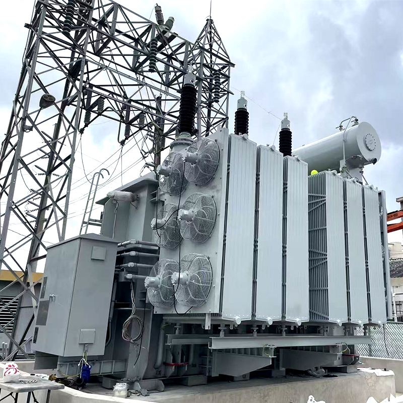
The body (windings and core) of an oil-immersed transformer is all installed in an oil tank filled with transformer oil, and the oil tank is welded with steel plates. The oil tank of medium and small-sized transformers is composed of a box shell and a box cover. The transformer body is placed inside the box shell. By opening the box cover, the transformer body can be lifted out for picking up and repairing. Large and medium-sized transformers, due to their large and heavy bodies, make it inconvenient to lift them. Therefore, they are all made into structures that can be lifted by box shells. This kind of box shell is just like a bell jar. When the instrument body needs maintenance, the lighter box shell, that is, the upper oil tank, is lifted off, and the entire instrument body is exposed.
The oil tanks of large-capacity transformers widely adopt a fully enclosed structure. That is, the main oil tank and the top steel plate of the oil tank or the upper oil tank and the lower oil tank are all welded together without using sealing gaskets to prevent unreliable sealing. For the convenience of maintenance, manhole doors or handhole doors are opened at appropriate positions.
4. Oil pillow
The oil pillow, also known as the oil storage cabinet, is an oil protection device. It is a cylindrical container made of mountain steel plate, horizontally installed on the cover of the transformer oil tank, and connected to the oil tank with a bent connecting pipe. One end of the oil pillow is equipped with an oil level gauge (oil gauge tube), through which the changes in the oil level can be monitored. The volume of the oil pillow is generally 8% to 10% of the volume of oil filled in the pressure reducer oil tank.
When the volume of the transformer oil expands or shrinks with the temperature of the oil, the oil conservator plays a role in storing and replenishing the oil, thus ensuring that the oil tank is filled with oil. At the same time, due to the installation of an oil pillow, the contact surface between the transformer oil and the air is reduced, thereby slowing down the deterioration rate of the oil.
Large transformers commonly use sealed oil plugs, which have the following two structures.
1) Diaphragm type oil pillow
The diaphragm type oil pillow uses a film (diaphragm) to isolate the oil from the atmosphere. The oil pillow is a horizontal cylinder. A thin film is sandwicized between the flange of the middle plane, dividing the internal space of the oil pillow into upper and lower parts. Below the film is transformer oil, and above the film is air. The material of the film is nylon fabric covered with nitrile butadiene rubber, which has extremely low air permeability, high oil resistance and low-temperature adaptability (-43 ℃). The lifespan of the film remains normal after being driven by an oil temperature of 60℃ for 100,000 times. The oil tank of the oil pillow can withstand full vacuum, so vacuum oil injection can still be achieved after the oil pillow is installed. A respirator is connected to the air side of the film and is in communication with the atmosphere.
2) Capsule-type oil pillow
The capsule-type oil pillow uses a synthetic rubber container in the upper space of the oil surface inside the oil pillow. There is no oil in the rubber container, while the remaining space inside the oil pillow is filled with transformer oil. The shape of the rubber container enables it to adapt to the changes in oil level caused by the thermal expansion and contraction of the oil through its shape variations. As this rubber container is made of nitrile rubber with excellent oil resistance, weather resistance and high mechanical strength, the device has sufficient reliability during long-term operation. Inside the rubber container, air is connected to the outside air through a moisture-absorbing filtering respirator to prevent the container from deteriorating. And always maintain atmospheric pressure in the rubber container. Furthermore, since the bottom of the rubber container was manufactured to be level with the oil quantity at that time, its bottom was indicated as the oil level by the oil level gauge.
5. Respirator
A respirator, also known as a moisture absorber, is usually composed of a pipe and a glass container, which contains a desiccant (silica gel or activated alumina). When the air in the oil pillow expands or shrinks with the volume of the transformer oil, the air discharged or sucked in all passes through the breather. The desiccant in the breather absorbs the moisture in the air and filters the air, thereby keeping the oil clean. Silica gel soaked in chlorinated diamonds has particles that are blue when dry. However, as the silica gel absorbs moisture and approaches saturation, the granular silica gel turns pinkish-white or red. Based on this, it can be determined whether the silica gel has lost its effectiveness. Silica gel that has been exposed to moisture can be regenerated by heating and drying. When the color of the silica gel particles turns cobalt blue, the regeneration process is completed.
6. Pressure relief device
Pressure relief devices play an important role in protecting power transformers. For power transformers filled with transformer oil, if there is an internal fault or short circuit, arc discharge will cause the oil to vaporize instantly, resulting in an extremely rapid increase in the pressure inside the oil tank. If the pressure cannot be released extremely quickly, the fuel tank will rupture, spraying flammable fuel over a large area, which may cause a fire and result in greater damage. Therefore, measures must be taken to prevent this from happening. There are two types of pressure relief devices: explosion-proof tubes and pressure relief devices. Explosion-proof tubes are used for small transformers, while pressure relief devices are used for large and medium-sized transformers.
Explosion-proof pipe (also known as fuel injection pipe)
The explosion-proof tube is installed on the top cover of the transformer. The bell-shaped tube is connected to the oil pillow or the atmosphere, and the tube opening is sealed with a film. When there is a fault inside the transformer, the oil temperature rises, and the oil decomposes violently to produce a large amount of gas, causing a sharp increase in the pressure inside the oil tank. When the pressure inside the oil tank rises to 50,000 Pa, the explosion-proof pipe film breaks, and the oil and gas spray out from the pipe opening to prevent the oil tank of the transformer from exploding or deforming.
2) Pressure relief device
Compared with explosion-proof tubes, pressure relief devices have the advantages of small opening pressure error, short delay time (only 2ms), high control temperature, and the ability to be used repeatedly. Therefore, they are widely used in large and medium-sized transformers.
The pressure relief device, also known as the pressure reducer, is installed on the top cover of the transformer oil tank, similar to the safety valve of a boiler. When the pressure inside the fuel tank exceeds the specified value, the sealing door (valve) of the pressure relief device is pushed open, and the gas is discharged. After the pressure decreases, the sealing door closes by itself due to the spring pressure. It can be disassembled before the pressure relief device is put into operation or during maintenance to measure and correct its operating pressure.
The adjustment of the operating pressure of the pressure relief device must be coordinated with the setting of the operating flow rate of the gas relay. Such as the movement of the pressure relief device


