Transformer "Structure, Light Gas, Heavy Gas Protection" and Accident Handling Guide
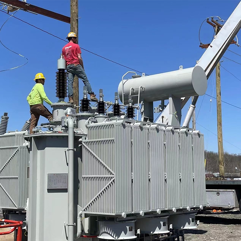
The main components and accessories of power transformers (oil-immersed type) :
1. Moisture absorber
The main function of the moisture absorber is to absorb moisture and impurities in the air to keep the transformer dry and operate smoothly, and to maintain the insulation performance of the transformer's insulating components.
The desiccant is filled with silica gel. The insulating oil in the oil storage tank (oil pillow) comes into contact with the air through the desiccant, allowing the desiccant to absorb moisture and impurities from the air. If the silica gel deteriorates or changes color, it can easily clog the desiccant, preventing the desiccant from coming into contact with the air.
2. Oil level gauge
An oil level gauge, as the name suggests, is a meter that reflects the changes in the oil level of a transformer. The oil level of the transformer is greatly affected by weather changes. In the hot summer, the transformer is under load, the oil temperature rises, and the oil level will also increase. However, in the cold winter, the oil temperature is lower, and when the load is light, the oil level fluctuation is smaller, and the oil level change is also smaller. The change of the oil level gauge is generally around +20℃, which is a normal phenomenon. When it's high, add oil; when it's low, add oil.
3. Oil pillow
The fuel filler is a container for storing fuel, which can adjust the fuel capacity in the tank and slow down the oxidation rate of the fuel. There is a filling hole at the top of it.
4. Explosion-proof pipe
Explosion-proof pipes belong to safety devices. The main purpose is to deal with the explosion accident caused by the increase in pressure inside the oil tank due to transformer failure.
5. Signal oil temperature gauge
The signal oil temperature gauge reflects the oil temperature on the upper layer of the transformer. Its main function is to monitor the changes in the operating temperature of the power transformer. The temperature of the transformer coil is 10℃ higher than that of the upper oil layer. According to the national standard, the maximum operating temperature of the transformer winding is 105℃. The maximum temperature on the upper layer should not exceed 95℃. Generally, it is better to set the monitoring temperature at 85℃ or below.
6. Tap changer
The tap changer can change the voltage ratio of the transformer's operation and ensure the normal operation of the transformer by increasing or decreasing the voltage ratio. It mainly works by changing the tap of the high-voltage winding.
7. Gas signal relay
Light gas and heavy gas signal protection. The upper contact is a light gas signal. When the transformer operates abnormally, it will issue an alarm signal. The lower contact is a heavy gas signal. After the light gas signal issues an alarm, it will complete the tripping, card dropping and alarm actions of the circuit breaker. When the gas relay is filled with oil, it indicates that there is no gas. When there is gas in the oil tank, it will enter the gas relay. When it reaches a certain capacity, the gas will push out the stored oil, causing the contacts to act. Insulating gloves must be worn when operating with power on.
Ii. Accident Handling of Transformers
1. Light gas protection action
The reasons for the generation of gas inside the transformer
1) The oil filtration, refueling or cooling system is not tight, causing air to enter the transformer and accumulate in the gas relay.
2) The oil level of the transformer drops and falls below the gas relay, allowing air to enter the gas relay.
3) A minor fault inside the transformer generates a small amount of gas.
4) It is normal for newly put into operation or overhauled transformers to have these situations. However, for transformers in normal operation, if the above abnormal phenomena occur, immediate analysis and handling should be carried out.
2. Handling of light gas protection actions
If it is caused by an excessively low oil level in the transformer, efforts should be made to eliminate it and restore the normal oil level.
2) If there is no gas, it is considered to be caused by a fault in the secondary circuit. At this time, switch the gas protection switch to the signal position. After checking that it is normal, switch the gas protection switch back to trip.
3) If it is found that the action of the light gas protection is caused by the accumulation of gas in the gas relay, the quantity of gas and the alarm time should be recorded, the gas should be collected for identification, and then corresponding measures should be taken based on the identification results.
3. Judgment and treatment of gas
If a gas is colorless, odorless and non-flammable, it is considered air.
2) If the gas is flammable and the chromatographic analysis is abnormal, it indicates that there is a fault inside the transformer. In this case, the transformer should be shut down.
3) When the gas is light gray, has a strong odor and is flammable, it may be a fault of the insulation material inside the transformer, and the transformer should be shut down.
4) If the gas is grayish black, black or flammable, it may be caused by the decomposition of transformer oil or the burning of the transformer core. The transformer should be shut down.
5) If the gas is slightly yellow and difficult to burn, it might be a fault of the essential material inside the transformer. The transformer should also be shut down.
6) Gas extraction methods for transformers. Use dedicated gas collection cylinders; There is approximately two-thirds of water in the gas collection (extraction) cylinder to ensure that the long tube is not submerged when the gas extraction cylinder is placed upside down. Use the first two tubes and hold them with small clips. Connect the long pipe of the gas collection bottle to the gas relay release valve, and open the small clamp of the short pipe of the gas collection bottle to drain water. After collection, secure the two small clips and conduct a ignition test at a safe location.
Ii. Handling of Heavy Gas Protection Actions
When a short circuit fault occurs inside the transformer, the arc at the fault point causes high temperatures, leading to the decomposition of insulating materials and transformer oil, generating a large amount of gas and causing rapid oil flow, which in turn triggers the action of the heavy gas relay.
When the heavy gas protection is activated, it is necessary to simultaneously check whether the differential protection and the quick-break protection are activated at the same time, and whether the explosion-proof door has already activated. And conduct an external inspection of the transformer, checking the oil level, oil temperature, explosion-proof door, breather, bushing, etc. of the transformer. At the same time, check whether there is any cracking sound or oil spraying inside the transformer. The specific handling is as follows:
Immediately check the transformer for any abnormal conditions such as oil spraying or fire damage.
2. Check whether there is any abnormal deformation of the transformer casing. Whether the oil surface of the oil pillow is normal.
3. Check whether the transformer leads are burned or short-circuited.
4. If no abnormalities are found after inspection and the gas is air, and the insulation of the measuring transformer is good, the secondary circuit should be inspected.
5. If it is determined that the malfunction is caused by the gas relay, the heavy gas protection should be shut down and the power supply restored by the method of stepwise pressurization, but the differential protection must be put into operation.
6. Take oil samples for chromatographic analysis.
7. Check if there is any sharp rise in the temperature of the transformer.
8. Take gas to determine the nature of the gas, take oil for testing, measure insulation, analyze the nature of the accident, find out the cause of the trip, and after obtaining the consent of the production plant director or chief engineer, gradually increase the pressure and supply power.
Iii. Handling of Differential Protection Actions
Check the detailed conditions of the primary equipment within the differential protection range. First, check for any fire. If there is a fire, put it out immediately.
2. Check whether the protection is due to malfunction or accidental contact by someone.
3. Check the differential circuit and relays.
4. Measure the insulation resistance of the transformer after the machine stops.
5. If no adverse phenomena are found during the inspection, start the unit after obtaining the consent of the deputy factory director in charge of production or the chief engineer. Gradually increase the pressure and contact the maintenance team to measure the differential pressure of the relay. Strengthen monitoring. If any abnormality is detected, immediately demagnetize and stop the machine.
6. After the stepwise pressurization test is successful. Power supply can be restored.
When heavy gas and differential protection operate simultaneously, the transformer shall not be put into operation until the cause is identified and the fault is eliminated.
Iv. Handling of Transformer Backup Protection Actions
When the backup protection is activated, if no voltage drop or impulse short circuit is found, the transformer can be put into operation without inspection and the maintenance personnel should be notified for inspection.
2. If there is a significant short-circuit impact phenomenon or other obvious phenomena while the overcurrent protection is activated, an external inspection of the primary system such as the transformer and busbar should be conducted. After identifying the cause and eliminating the fault, and measuring that the insulation of the transformer is qualified, the transformer should be put back into operation. If it is determined that the fault is caused by an external short-circuit fault and the faulty equipment has been isolated, and the system is necessary, the transformer can be put back into operation without external inspection.
V. Handling of Transformer Fire
Cut off the power supply to the burning transformer.
2. Shut down the cooling system or the power supply of the fan.
3. If the transformer oil overflows on the top cover and catches fire, the oil valve at the bottom should be opened to release the oil to an appropriate level, and the fire can be extinguished with carbon dioxide or carbon tetrachloride.
When the fire is large, water can be used to put it out.
5. If the fuel tank ruptures, the fuel is sprayed and catches fire, and the external fire is very large, the fuel can only be discharged into the accident fuel drainage corridor. Oil fires on the ground should be extinguished with a large amount of foam fire extinguishing agent.
6. After a fire breaks out, it is necessary to prevent the burning oil from flowing into the cable trench and other production sites.


