The principle, structure and operation and maintenance of transformer gas protection.
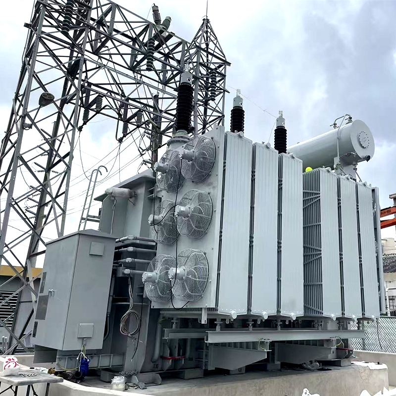
Gas protection is the main protection against internal faults in transformers. It can sensitively act on faults such as inter-turn and inter-layer short circuits, core faults, internal faults in bushings, internal open wires in windings, insulation deterioration and oil level drop. When an internal fault occurs in an oil-immersed transformer, the arc will cause the insulating material to decompose and generate a large amount of gas, which flows from the oil tank to the oil pillow. The intensity of this gas flow varies with the severity of the fault. The protection that acts in response to this gas flow and oil flow is called gas protection, also known as gas protection. During the operation of a transformer, due to internal faults, sometimes we cannot identify and take measures in time, which can easily lead to some accidents. After adopting gas relay protection, similar incidents can be avoided to a certain extent.
I. What is gas?
Gas is produced by the decomposition of cellulose and organic matter by anaerobic bacteria in the early stage of ancient plants piling up to form coal. In a high-temperature and high-pressure environment, while coal is being formed, gas continues to be generated due to physical and chemical actions. Gas is a colorless and odorless gas, but sometimes a fragrance similar to that of apples can be detected. This is because aromatic hydrocarbon gases are released simultaneously with gas. The relative density of gas to air is 0.554. Under standard conditions, the density of gas is 0.716kg/m³. The permeability of gas is 1.6 times that of air. It is insoluble in water, does not support combustion and cannot sustain breathing. When it reaches a certain concentration, it can cause suffocation due to lack of oxygen and can also cause combustion or explosion.
The main component of gas is alkanes, with methane accounting for the vast majority. There are also small amounts of ethane, propane and butane. In addition, it generally contains hydrogen sulfide, carbon dioxide, nitrogen and water vapor, as well as trace amounts of inert gases such as helium and argon. Under standard conditions, methane to butane exist in gaseous form, while pentane and above are in liquid form. If exposed to open flames, it can catch fire and cause a "gas" explosion, directly threatening the lives and safety of miners.
Ii. Definition of Gas Protection
Inside the gas protection relay, there is a sealed float at the top and a metal baffle at the bottom. Both are equipped with sealed mercury contacts. The float and the baffle can rotate around their respective axes. During normal operation, the relay is filled with oil, the float is immersed in the oil and is in the floating position, and the mercury contact is disconnected. The baffle droops due to its own weight, and its mercury contacts are also disconnected. When a minor fault occurs inside the transformer, the gas is generated at a relatively slow rate. As the gas rises to the oil storage tank, it first accumulates in the upper space of the gas relay, causing the oil level to drop. The float then descends, closing the mercury contact and triggering a delay signal. This is what is known as "light gas". When a serious fault occurs inside the transformer, a strong amount of gas is produced. The pressure inside the oil tank suddenly increases, generating a large oil flow that impacts the oil bolster. As the oil flow impacts the baffle, the baffle overcomes the resistance of the spring, driving the magnet to move towards the spring contact, causing the mercury contact to close and connecting the trip circuit, tripping the circuit breaker. This is what is called "heavy gas". In case of a heavy gas incident, immediately cut off all power supplies connected to the transformer to prevent the accident from escalating and protect the transformer.
Gas relays come in different types such as float type, baffle type, and open cup type. Most of them adopt the QJ-80 type relay, whose signal circuit is connected to the open cup and the trip circuit is connected to the baffle. The so-called gas protection signal action refers to the situation where the signal circuit contact of the upper open cup inside the relay closes due to various reasons, and the light sign lights up.
The regulations stipulate that for oil-immersed transformers with a capacity of 800kVA and above and oil-immersed transformers in workshops with a capacity of 400kVA and above, gas protection should be installed.
Iii. Classification of Gas Protection
Gas protection is generally divided into two categories: light gas and heavy gas.
1. Light gas protection: Overheating or partial discharge inside the transformer causes the oil temperature of the transformer to rise, generating a certain amount of gas. This gas accumulates in the relay. Once it reaches a certain amount, the relay is triggered to send out a signal.
2. Heavy gas protection: After a severe short circuit occurs inside the transformer, it will impact the transformer oil, causing a certain amount of oil flow to rush towards the relay baffle, which will trigger a trip.
Iv. Protection Range of Gas Protection
Gas protection is the main protection for transformers, which can reflect all faults in the oil tank. This includes: multiphase short circuits in the oil tank, inter-turn short circuits in the windings, short circuits between the windings and the core or the casing, core faults, oil level drops or oil leakage, poor contact of the tap changer or poor welding of the wires, etc. The gas protection operates quickly, is sensitive and reliable, and has a simple structure. However, it cannot reflect the faults of the external circuit of the fuel tank (such as the lead-out line), so it cannot be used as the sole protective device against internal faults of the transformer. In addition, gas protection is also prone to malfunction under the interference of some external factors (such as earthquakes).
The gas relay of the on-load voltage regulating switch of the transformer has the same function as that of the main transformer, but they are installed in different positions and have different models.
Five, the installation method of protection
The gas relay is installed on the connection pipeline from the transformer to the oil storage tank. When installing, attention should be paid to:
First, close the disc valve on the gas relay pipeline tightly. If the disc valve does not close tightly or there are other circumstances, the oil in the oil pillow can be drained when necessary to prevent a large amount of oil from overflowing during operation.
Before installing a new gas relay, it is necessary to check whether there is a certificate of inspection qualification, whether the diameter and flow rate are correct, whether the internal and external components are damaged, and if there are any temporary bindings inside, they should be removed. Finally, check whether the float, baffle plate, signal and trip contact actions are reliable, and close the gas release valve.
3. The gas relay should be installed horizontally. The arrow direction marked on the top cover should point towards the oil pillow. In the project, the end of the relay's pipeline axis direction towards the oil pillow is allowed to be slightly higher, but the inclination from the horizontal plane should not exceed 4%.
4. Open the disc valve to fill the gas relay with oil. After it is fully filled with oil, release the gas through the gas release valve. If the oil pillow contains capsules, attention should be paid to the method of filling with oil and releasing air to minimize and avoid the entry of gas into the oil pillow as much as possible.
When performing protective wiring, it is necessary to prevent incorrect connection and short circuit, avoid live operation, and at the same time prevent the conductive rod from rotating and the small porcelain head from leaking oil.
Before being put into operation, insulation shaking tests and transmission tests should be conducted.
Vi. Test Items for Gas Relays
Before installation and use, gas relays should undergo the following inspection and test items:
1. General inspection items: The glass window, air release valve, control pin and lead wire terminal, etc. are intact and free of oil leakage; the float, open cup, glass window, etc. are intact and free of cracks.
2. Test items
2.1 Sealing test: Conduct a leak test under overall oil pressure (with a pressure of 20mPa and a duration of 1 hour), and there should be no seepage leakage.
2.2 Terminal insulation strength test: The outgoing terminals and the terminals between them can withstand a power frequency voltage of 2000v for 1 minute. Alternatively, a 2500v megohmmeter can be used to measure the insulation resistance. Measuring for 1 minute can replace the power frequency withstand voltage. The insulation resistance should be above 300mΩ.
2.3 Light gas action Volume test: When 250 to 300cm ³ of air accumulates in the shell, the light gas should act reliably.
2.4 Heavy gas action flow rate test.
Vii. Daily Inspection
The Operating Regulations for Power Transformers DL/T572-95 (hereinafter referred to as the "Regulations") stipulates that in the daily inspection items of transformers, the first step should be to check whether there is gas in the gas relay. For the inspection of gas, the following points should be emphasized:
The valve on the connection pipe of the gas relay should be in the open position.
2. The breather of the transformer should be in a normal working condition.
3. The connection plates for gas protection should be inserted correctly.
4. The oil level of the oil pillow should be at an appropriate position, and the relay should be fully filled with oil.
5. The waterproof cover of the gas relay must be firm.
6. There should be no oil leakage at the relay terminal, and it should be able to prevent the intrusion of rain, snow and dust. The power supply and its secondary circuit should have waterproof, oil-proof and anti-freezing measures, and waterproof, oil-proof and anti-freezing checks should be carried out in spring and autumn.
Eight, Operation of Gas protection
When the transformer is operating normally, the gas relay works without any abnormality. Regarding the operating status of gas relays, the regulations stipulate the following:
When the transformer is in operation, the gas protection should be connected to the signal and trip, and the gas protection of the on-load tap changer should be connected to the trip.
2. When the transformer is in operation and performing the following tasks, the heavy gas protection should be reconnected to the signal:
When one circuit breaker controls two transformers and one of them is switched to standby, the heavy gas of the standby transformer should be reconnected to the signal.
2.2 When filtering oil, replenishing oil, replacing the submersible oil pump or the adsorbent of the oil purifier, and opening or closing the valve on the connection pipe of the gas relay.
2.3 When working on gas protection and its secondary circuits.
2.4 When opening the air release, oil release and oil inlet valves at all other locations except for the oil sample collection and the air release valve at the upper part of the gas relay.
2.5 When the oil level of the oil gauge abnormally rises or there are abnormal phenomena in the suction system, and it is necessary to open the air release or oil release valve.
During the earthquake warning period, the operation mode of heavy gas protection should be determined based on the specific conditions of the transformer and the seismic performance of the gas relay. Transformers that have been shut down due to heavy gas protection actions caused by earthquakes should have their transformers and gas protection inspected and tested before being put into operation. Only after confirming that there are no abnormalities can they be put back into use.
Ix. Reasons for the Action of Gas protection
The reasons for the light gas action
1.1 Air enters the transformer due to loose oil filtration, refueling or cooling systems.
1.2. Due to temperature drop or oil leakage, the oil level is below the light gas float of the gas relay
1.3 A small amount of gas is produced due to transformer failure
1.4. A through-circuit fault occurred in the transformer. Under the action of through-fault current, the oil flow velocity between the oil gaps increases. When the pressure difference generated inside the oil gap and outside the winding changes greatly, the gas relay may malfunction. The through-fault current causes the winding to operate and heat up. When the multiple of the fault current is very large, the winding temperature rises rapidly, causing the volume of the oil to expand and resulting in the malfunction of the gas relay.
1.5. Faults in gas relays or secondary circuits. All the factors mentioned above may cause the gas protection signal to act.
X. Handling after Gas protection Actions
After the gas protection device of the transformer operates, it should be carefully inspected, analyzed and accurately judged immediately, and immediate handling measures should be taken.
When the gas protection signal operates, immediately inspect the transformer to determine the cause of the operation, whether it is due to accumulated air, A drop in oil level, a fault in the secondary circuit, or an internal fault in the upper transformer. If there is gas in the gas relay, the gas volume should be recorded, the color of the gas observed and whether it is flammable tested. Gas samples and oil samples should be taken for chromatographic analysis. The nature of the transformer fault can be determined according to relevant regulations and guidelines. Chromatographic analysis refers to the qualitative and quantitative analysis of collected gases such as hydrogen, oxygen, carbon monoxide, carbon dioxide, methane, ethane, ethylene, and acetylene using a chromatograph. Based on the names and contents of the components, it accurately determines the nature, development trend, and severity of the fault.
B. If the gas inside the gas relay is colorless, odorless and non-flammable, and is determined to be air by chromatographic analysis, the transformer can continue to operate and the gas inlet defect should be eliminated in time.
If the gas inside the gas relay is flammable and the chromatographic analysis results of the dissolved gas in the oil are abnormal, a comprehensive judgment should be made to determine whether the transformer has been shut down.
When the gas relay trips, the transformer must not be put into operation until the cause is identified and the fault is eliminated. To identify the cause, the following factors should be given priority consideration and a comprehensive judgment should be made.
a. Whether there is difficulty in breathing or incomplete exhaust;
b. Whether the secondary circuits such as protection and DC are normal;
c. Whether there are any abnormal phenomena on the appearance of the transformer that obviously reflect the nature of the fault;
d. Whether the gas accumulated in the gas relay is flammable; e. Chromatographic analysis results of the gas in the gas relay and the dissolved gas in the oil;
f. Necessary electrical test results;
g. The operating conditions of other relay protection devices of the transformer.
Xi. Safety Measures for gas protection
The gas protection action, in mild cases, sends out a protection action signal to remind the maintenance personnel to deal with the transformer immediately. In severe cases, the transformer switch is tripped, causing the transformer to stop operating immediately and failing to ensure the reliability of power supply. In response to this, anti-accident measures for gas protection are proposed:
1. Change the lower float of the gas relay to a baffle type and the contacts to a vertical type to enhance the reliability of heavy gas operation.
To prevent the gas relay from short-circuiting due to water leakage, rainproof measures should be taken on its terminals and the terminal box of the cable lead.
3. The lead-out wires of the gas relay should be oil-proof wires.
4. The lead wires and cables of the gas relay should be respectively connected to the terminals in the cable lead terminal box.


