Comprehensive Knowledge of Three-phase Oil-immersed Transformers
(1) Core
The core is the magnetic circuit part of the transformer. To reduce the hysteresis and eddy current losses in the core, the core is composed of silicon steel sheets with a thickness of 0.35mm to 0.5mm. The surface of the silicon steel sheets is coated with insulating varnish or the surface oxide film is used to insulate the sheets from each other. The vertical part of the core of a three-phase transformer is called the core column, on which the low-voltage winding and high-voltage winding of the transformer are wound. The horizontal part is called the yoke and is used to form a closed magnetic circuit.
(2) Winding
Windings, also known as coils, are the circuit components of a transformer and are divided into primary and secondary windings. Among them, the winding connected to the power supply is called the primary winding, and the winding connected to the load is called the secondary winding. Both the primary and secondary windings are wound with copper or aluminum wires wrapped with high-strength insulating materials. In a three-phase transformer, the primary and secondary windings of each phase are made in a cylindrical shape and wound around the same core column. The low-voltage winding with fewer turns is wound inside and close to the core, while the high-voltage winding with more turns is wound outside the low-voltage winding. It is placed this way because the low-voltage winding is relatively easy to insulate the core. The low-voltage winding and the core, as well as the high-voltage winding and the low-voltage winding, are all isolated by sleeves made of insulating materials to reliably insulate them. To facilitate heat dissipation, a certain gap is left between the high and low windings as an oil passage, allowing the transformer oil to flow.
(3) Fuel tank
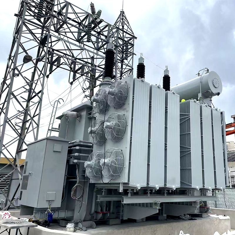
The oil tank is the casing of the transformer, where the core and windings are all installed and filled with transformer oil. For transformers with relatively large capacity, heat sinks or heat dissipation tubes are installed outside the oil tank.
Transformer oil is a kind of mineral oil with good insulating performance. It has two functions: one is the insulating function. The insulating performance of transformer oil is better than that of air. When the windings are immersed in the oil, the insulating performance of all parts can be improved, and contact with air can be avoided to prevent the windings from getting damp. The second function is heat dissipation. By taking advantage of the convection of oil, the heat generated by the core and windings is dissipated to the outside through the box wall and heat dissipation tubes. Transformer oil is classified into three specifications based on its freezing point: No. 10, No. 25, and No. 45. Their freezing points are -10℃, -25℃, and -45℃ respectively. Generally, it is selected according to local climatic conditions.
(4) Oil storage tank
The oil storage tank, commonly known as the oil pillow, is a cylindrical container placed horizontally above the oil tank and connected to the oil tank of the transformer through pipes. The volume of the oil storage tank is generally about 10% of the volume of the oil tank. This oil storage tank is a capsule-type oil storage tank. The capsules isolate the oil inside the oil storage tank from the outside air. When the transformer oil expands due to heat, the oil flows from the oil tank to the oil storage tank. When the transformer oil shrinks, the oil flows from the oil storage tank to the oil tank. The oil storage tank has two functions: Firstly, when the volume of the transformer oil expands or shrinks with the change of oil temperature, the oil storage tank serves to store and replenish the oil, ensuring that the oil tank is filled with oil and that the core and windings are immersed in the oil. Second, it can reduce the contact area between the oil surface and the air, preventing the transformer oil from getting damp and deteriorating.
The oil level display of the oil storage tank adopts a connecting rod type ferromagnetic oil level gauge to observe the height of the oil surface. When the oil quantity is insufficient due to leakage or other reasons, oil should be replenished in time. The oil level gauge is engraved with the standard lines of oil level height when the oil temperature is -30℃, +20℃ and +40℃, which serve as the standards for oil filling. The oil level mark of +40℃ indicates the maximum limit line of the oil level when the transformer at the installation location operates at full load when the ambient maximum temperature is +40℃. The oil level must not exceed this line. +20℃ indicates the oil level height during full-load operation when the annual average temperature is +20℃. -30℃ indicates the minimum oil level line of the no-load transformer when the environment is -30℃. It must not be lower than this line. If the oil level is too low, oil should be added. The oil sleeper is equipped with breathing holes, allowing the upper space of the oil sleeper to communicate with the atmosphere. When the transformer oil expands and contracts due to temperature changes, the air at the upper part of the oil pillow enters and exits through the breathing holes, allowing the oil level to rise or fall, preventing the oil tank from deforming or being damaged.
(5) Casing
The lead-out wires of the transformer winding are connected to the external circuit through the guide rods. The bushing is an insulator between the guide rods and the box cover, which serves to insulate and fix the guide rods. There are two types of sleeves: high-pressure sleeves and low-pressure sleeves.
(6) Explosion-proof pipe
Explosion-proof tubes are installed on the transformer box cover. When a sudden and severe fault occurs inside the transformer, the pressure inside the oil tank will rise rapidly. To prevent an oil tank explosion accident caused by excessive pressure increase. After the action, the internal pressure of the box is released and the contact is connected for alarm or tripping.
(7) Gas relay for gas
The gas relay is installed between the connecting pipe of the oil storage tank and the transformer oil tank cover by using a flange. During operation, the gas relay is filled with oil. When a minor fault occurs inside the transformer and bubbles are produced, they will first accumulate in the upper space of the gas relay and force the oil level to drop, causing the upper opening cup to lose buoyancy and its own mass to increase, thus reversing. Bring the magnet close to the reed switch to act. The principle of the lower contact baffle type is the same.
(8) Temperature measurement device
The oil surface temperature rise refers to the value by which the oil surface temperature in the oil tank of the transformer is allowed to exceed the ambient temperature when it is operating under rated conditions.
The oil temperature of the main transformer body is temporarily set to alarm at 80℃ and trip at 100℃.
(9) Neutral point grounding switch
In China's 110kV power system, the neutral point grounding method mainly adopts the direct grounding method of the neutral point (including the grounding method of the neutral point through a small resistance), that is, the large grounding current system. Because when a single-phase grounding fault occurs in the system, the grounding short-circuit current is very large.
When a transformer is powered on or off, its neutral point must be grounded. Because the winding of this transformer is semi-insulated (also known as staged insulation), that is, the main insulation of the winding near the neutral point of the transformer has a lower insulation level than that at the end of the winding. Therefore, to prevent overvoltage from damaging the insulation of the transformer, when the transformer is powered on or off, its neutral point must be grounded.
(10) Tap changer
When the oil storage tank is used for on-load tap-changing transformers, a capsule-free switch oil storage tank is installed at the bottom of the oil storage tank.
There are two types of transformer voltage regulation methods: on-load voltage regulation and no-load voltage regulation.
On-load voltage regulation refers to the ability of a transformer to adjust the position of its tap during operation, thereby changing the transformer's transformation ratio to achieve the purpose of voltage regulation.
Transformer taps are generally drawn from the high-voltage side, mainly considering:
(1) The high-voltage winding of the transformer is generally on the outside, and the tap leads out for connection, which is convenient.
(2) The current on the high-voltage side is smaller, and the conductor cross-sectional area of the lead-out wire and the current-carrying part of the branch switch is smaller, making it easier to solve the problem of poor contact.
In principle, the tap can be drawn from either side, but an economic and technical comparison is required. For instance, the tap of a 500kV large step-down transformer is drawn from the 220kV side, while the 500kV side is fixed.
When the voltage is too low or too high and several taps of the on-load tap changer need to be adjusted to meet the requirements, the following situations need to be particularly noted:
It should be adjusted step by step. That is, for each press of the N+1 or N-1 button, pause for 1 minute in the middle. When a new number appears on the gear indicator, press the button again. Repeat the above process in sequence until the final goal is reached. When the electric operation shows a linkage phenomenon (i.e., one operation will result in the adjustment of more than one tap, commonly known as sliding gear), the emergency stop button should be pressed immediately after the position of the second tap appears on the gear position indicator of the main transformer control panel, and then the operation should be changed to manual operation.


